I have recently discovered Nanoframework which is a community-led project to bring C# and Dotnet to the world of micro-controllers. Since then, I have been tinkering with IoT and embedded devices using C# to connect with sensors and play around with them.
One of the sensors I wanted to try out was the DHT22. This sensor has 3 pins you need to connect: a VCC pin (3.3v to 5.5v), a signal/trigger pin, and a ground pin.
When I tried to connect this sensor to my ESP32 board and write some simple code to query for the temperature, I realized things weren’t as straight forward as connecting 3 pins. The reason for that is switching the signal/trigger pin mode from input to output can’t be done fast enough and the DHT22 sensor relies heavily on accurate timing when sending the signal carrying the data. This issue is on Windows 10 IoT core and since the DHTxx library was ported from dotnet-iot to nanoframework, this quirk was brought over.
Following some schematics online and reading docs, I was able to build a simple “weather station” using the DHT22 and a PCD8544 LCD (The Nokia 5110 LCD) with C# code running on my ESP32 board.
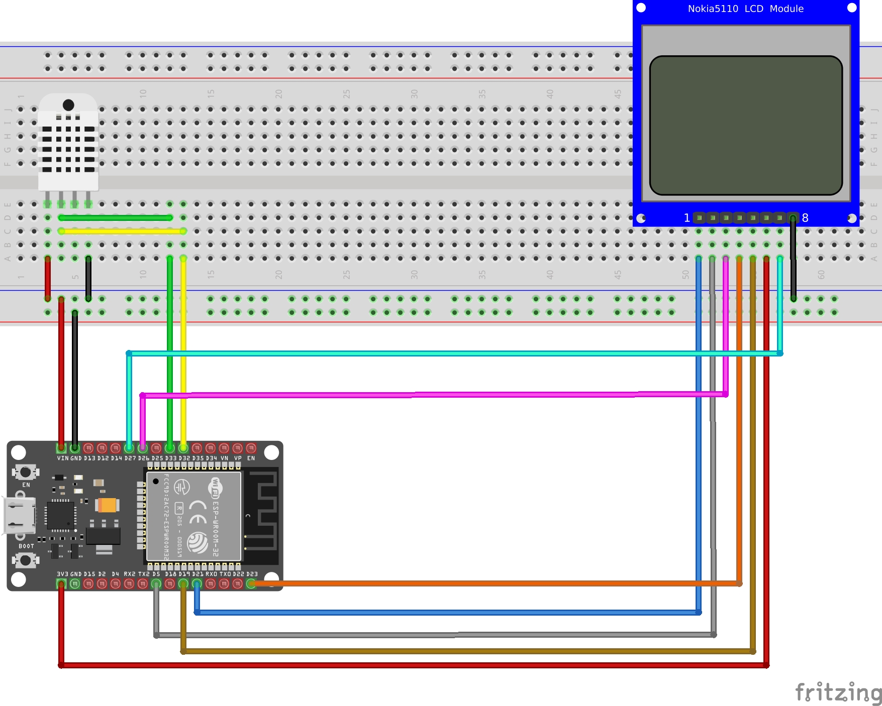
Schematics
Let’s start with the schematics of this project. This is how I have wired the components. You can see how I have 2 pins hooked to the signal/trigger pin on the DHT22 (Green & Yellow wires). Feel free to open the image below in a new tab. The ESP32 board’s pins are labelled and you can follow the wires easily.
Code
Create a new nanoframework project. You can follow the instructions here.
Install the following nuget packages:
Install-Package nanoFramework.Iot.Device.Dhtxx.Esp32 -Version 1.2.73
Install-Package nanoFramework.Iot.Device.Pcd8544 -Version 1.0.1
(Please note that if you are not using an ESP32 board, you should be using nanoFramework.Iot.Device.Dhtxx instead.)
Once that is done, let’s define the pins we will use:
var lcdResetPin = 21;
var lcdDataCommandPin = 26;
var lcdBacklightPin = 27;
var lcdChipSelectLinePin = 5;
var dhtEchoPin = 33;
var dhtTriggerPin = 32;
var lcdSpiBusId = 1;
The pins defined above are for communication with the LCD and the DHT22 sensor.
Next, let’s create the GpioController, SpiDevice, Pcd8544, and Dht22 objects:
var gpioController = new GpioController();
var spiConnectionSettings = new SpiConnectionSettings(lcdSpiBusId, lcdChipSelectLinePin)
{
    ClockFrequency = 5_000_000,
    Mode = SpiMode.Mode0,
    DataFlow = DataFlow.MsbFirst,
    ChipSelectLineActiveState = PinValue.Low
};
var spiDevice = new SpiDevice(spiConnectionSettings);

var lcd = new Pcd8544(lcdDataCommandPin, spiDevice, lcdResetPin, lcdBacklightPin, gpioController, false);
lcd.Enabled = true;
lcd.Bias = 6;
lcd.Contrast = 40;
lcd.BacklightOn = true;

var dhtSensor = new Dht22(dhtEchoPin, dhtTriggerPin, gpioController: gpioController);
The GpioController is needed by the Dht22 instance so it can control the LCD data command and backlight pins while SpiDevice is needed to send the display buffer
Now we can query the Dht22 instance for the temperature and humidity levels then display that on the LCD:
while (true)
{
Thread.Sleep(2000);
var temp = dhtSensor.Temperature;
var hum = dhtSensor.Humidity;
if (!dhtSensor.IsLastReadSuccessful)
{
lcd.Clear();
lcd.WriteLine("FAILED TO READ SENSOR");
continue;
}
lcd.Clear();
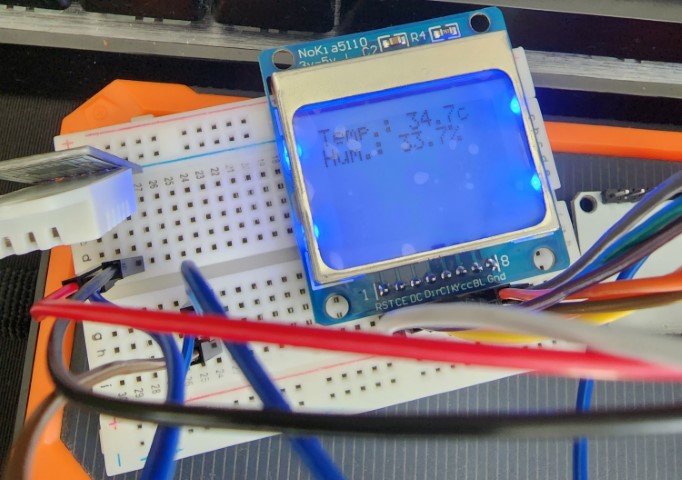
lcd.WriteLine($"Temp.: {temp.DegreesCelsius}c");
lcd.WriteLine($"Hum.: {hum.Percent}%");
}
Inside the loop, there is a Thread.Sleep(2000). The reason for this is that the DHT22 provides measurements every 1.7 seconds.
The next 2 lines query the sensor for the temperature and humidity level. After that, we have to check if the operation was a success. The DHT22 implementation doesn’t throw exception if a read has failed. Instead, it updates the IsLastReadSuccessful flag. In the code above, if the read operation was not successful, we display an error message on the lcd, otherwise we display the readings and repeat the loop again.
The final result: